








برش و پانچ در عناصر RC و FRC
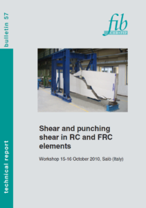
This article develops the subject of the supplied extract using supplementary technical sources, including fib Bulletin 57. That publication contains proceedings from the October 2010 Salò workshop. References to helping formulate Model Code 2010 belong to that historical context, rather than a current drafting process. The discussion below is an independent scientific overview, not a translation of the complete publication.

Shear and Punching Shear in RC and FRC Elements concerns how forces cross cracked concrete and how reinforcement influences that transfer. RC normally refers to concrete with conventional reinforcing bars. FRC contains distributed fibres; it may also contain bars, stirrups, or prestressing tendons. These categories therefore overlap rather than describe mutually exclusive structural systems.
Steel fibres can improve post-cracking tensile behaviour when their geometry, distribution, and bond are suitable. They do not make concrete uncrackable or automatically replace conventional reinforcement. Structural use depends on measured performance, the member configuration, and the applicable design provisions.
Shear and Punching Shear in RC and FRC Elements involves two related but different problems. In beams, one-way shear is associated with force transfer through a member and often with inclined cracking. Aggregate interlock, the compression region, reinforcement action, and residual tensile transfer can contribute, with their relative importance changing as cracks open.
Punching is a two-way action around concentrated loads or supports, such as slab–column connections. Slab rotation, effective depth, column geometry, reinforcement, and load transfer affect the response. Openings, edge locations, and unbalanced moments can alter the stress field substantially.
A beam shear result should not be transferred directly to slab punching. Likewise, an increase in flexural toughness does not establish a corresponding percentage increase in punching resistance. The relevant limit state and geometry must be assessed explicitly.

Shear and Punching Shear in RC and FRC Elements requires attention to crack opening, not just the load at first cracking. Fibres crossing a crack can transfer tensile forces as the surrounding matrix separates. Their response involves debonding, frictional sliding, mechanical anchorage, and sometimes fibre rupture.
Hooked ends can increase anchorage, but performance depends on embedment, orientation, fibre strength, and matrix behaviour. A strong matrix does not guarantee the desired pull-out response; premature rupture or local matrix damage can change the energy absorbed.
Fibre dosage alone cannot describe this response. Two concretes containing the same mass of fibres may develop different residual strengths because of fibre geometry, distribution, casting direction, and workability. Tests must characterize the proposed material rather than assume a universal dosage-to-capacity relationship.
| Material or reinforcement system | Principal contribution | Important limitation |
|---|---|---|
| Concrete matrix | Compression transfer and crack-related mechanisms | Tensile resistance changes markedly after cracking |
| Longitudinal bars | Flexural resistance and interaction with shear transfer | Anchorage and detailing remain essential |
| Stirrups or dedicated shear reinforcement | Designed transfer across potential shear cracks | Effectiveness depends on layout and anchorage |
| Steel fibres | Distributed post-cracking tensile transfer | Orientation and residual performance must be established |
| Prestressing | Changes stress state and crack development | Shear and anchorage checks remain necessary |
Shear and Punching Shear in RC and FRC Elements also depends on the matrix surrounding each fibre. Cement hydration forms binding products, including calcium silicate hydrate, commonly abbreviated C-S-H. Its composition is variable; a single fixed molecular formula cannot represent every cementitious system.
The interfacial region can differ from bulk paste because particle packing and hydration develop around the fibre surface. Porosity, curing, supplementary cementitious materials, and local microcracking influence this region. Changes in interface quality can modify bond and pull-out behaviour without producing an equivalent change in compressive strength.
Reactive silica in suitable supplementary cementitious materials can react with portlandite and water to form additional calcium silicate hydrate. Changes in particle packing and hydration may modify the fibre interface. However, an optimum binder composition cannot be inferred from compressive strength alone: interfacial pull-out tests and relevant residual-performance tests remain necessary. Research on silica-fume-containing ultra-high-strength matrices illustrates this material-specific relationship.
The main structural contribution of a steel fibre remains mechanical crack bridging. It should not be described as a new chemical bond that prevents all cracking. Chemical and microstructural conditions influence the interface through which those mechanical forces are transferred.

Shear and Punching Shear in RC and FRC Elements should be considered over the intended exposure and service life. The alkaline environment of sound concrete can support passivation of embedded steel. Carbonation and chloride exposure can compromise that protection under relevant conditions.
Fibres exposed at surfaces or crossing cracks may experience different conditions from fibres fully embedded in dense paste. Corrosion effects depend on exposure, crack width, fibre material, and time; neither inevitable rapid failure nor permanent immunity should be assumed.
Adequate curing supports matrix development and helps limit early drying damage. Water reducers can improve placement at a controlled water content, but compatibility and fibre dispersion still require attention. Adding water to compensate for a harsh fibre mixture can undermine the intended matrix quality.
Shear and Punching Shear in RC and FRC Elements benefits from tests that describe behaviour after cracking. EN 14651 and ASTM C1609 use different specimen and measurement arrangements. Their reported residual values should not be treated as interchangeable without a justified relationship.
ASTM C1609 evaluates flexural performance using a beam under third-point loading. Its residual-strength measurements characterize response after cracking at specified deflections. EN 14651 uses a notched-beam procedure and crack-mouth-opening measurements. Flexural residual strength is not automatically a direct tensile constitutive law; converting test results into design input requires an appropriate model.
Representative testing should also address production variability. Specimen preparation and casting can influence fibre orientation. Laboratory performance should be supported by production controls so that the supplied material corresponds to the design assumptions.
| Assessment | What it establishes | What it does not establish alone |
|---|---|---|
| Compressive-strength test | Matrix compressive performance at a stated age | Post-cracking fibre contribution |
| Residual flexural test | Response at specified deflections or crack openings | Universal member shear or punching capacity |
| Fibre-content and distribution checks | Consistency with production requirements | Effective orientation across every potential crack |
| Relevant member test | Response of a defined structural configuration | Validity for every depth, support, or loading arrangement |
| Durability assessment | Behaviour under selected exposure conditions | Unlimited service life or immunity to corrosion |
Shear and Punching Shear in RC and FRC Elements includes both prestressed and non-prestressed members. Prestressing changes the stress state and can delay some crack development. Its effects depend on tendon profile, force, losses, and load introduction. End regions, anchorage zones, and construction stages still need appropriate checks.
Member size also matters. A small specimen and a full-scale beam or slab need not develop the same nominal failure stress. Crack development, aggregate dimensions, reinforcement ratios, and boundary conditions influence interpretation. Results should be compared within a relevant range rather than scaled using compressive strength alone.

Shear and Punching Shear in RC and FRC Elements remains sensitive to the selected analytical approach. Models may represent crack kinematics, compression fields, fracture processes, or combinations of mechanisms. Their inputs and calibration limits should be understood before applying them to an unfamiliar material or geometry.
Fibre contributions must be included consistently. Adding a separate fibre resistance to a concrete term already calibrated for the same contribution risks double counting. Safety factors, residual-strength definitions, and detailing requirements must come from the applicable design framework rather than a mixture of incompatible equations.
Fibres may replace some conventional shear reinforcement only where the governing provisions permit it and all relevant requirements are satisfied. A successful research specimen does not establish general permission to omit stirrups or punching reinforcement in construction.
Shear and Punching Shear in RC and FRC Elements is ultimately a link between material characterization and structural verification. Specify the required residual performance, test method, acceptance rules, mixture controls, and reinforcement details. Review load combinations, deflection, cracking, stability, and the relevant ultimate limit states.
Document fibre type, batching, mixing sequence, workability, placement, and curing. Investigate production changes that could alter dispersion or orientation. The objective is a reliable member response supported by evidence, rather than a generic claim that adding fibres makes every shear-critical structure safer.
Image 5 — Editorial poster
Conceptual illustration of fibre crack bridging. The enlarged fibres and arrows explain the mechanism; they do not represent a microscopic image, measured stress field, or numerical analysis result.
For further materials information and technical consultation, visit Betono and Iran Concrete.
fib: Bulletin 57 — Shear and punching shear in RC and FRC elements, workshop proceedings, 2010.
fib: Bulletin 105 — Fibre Reinforced Concrete, 2022.
ASTM: C1609/C1609M — Flexural Performance of Fiber-Reinforced Concrete.
Research article: Influence of silica fume content on microstructure development and bond to steel fiber in ultra-high strength cement-based materials.
 Innovative Materials and Techniques in Concrete Construction مواد و تکنیک های نوآورانه در ساخت و ساز بتنی
 Seismic Design of Concrete Buildings to Eurocode 8_طراحی لرزه ای ازساختمان های بتنی یورو 8
 Guide to Diagnosis and Appraisal of AAR Damage to Concrete in Structures_راهنمای تشخیص وارزیابی AAR آسیب به بتن در سازه ها
 FINITE ELEMENT ANALYSIS AND DESIGN OF STEEL AND STEEL–CONCRETE COMPOSITE BRIDGE_المان محدود تجزیه و تحلیل و طراحی از فولاد
 Handbook of recycled concrete and demolition waste_ کتاب راهنمای بتن بازیافتی و ضایعات تخریب
 HANDBOOK OF LOW CARBON CONCRETE_ راهنمای بتن کم کربن
 Improving Concrete Quality_بهبود کیفیت بتن
 Concrete Fracture_ شکستگی بتن
 Control of Cracking in Reinforced Concrete Structures _ کنترل ترک خوردگی در سازه های بتنی مسلح
 SUPER-HIGH-STRENGTH HIGH PERFORMANCE CONCRETE_ بتن با عملکرد فوق العاده بالا
 Advanced Polymer Concretes and Compounds_بتن های پلیمری پیشرفته و اجزای آن
 Concrete Construction_ ساخت و ساز بتنی